How to assemble a flashing stop signal?
Anyone who watches Formula 1 races has noticed that many cars have brake lights flashing. That is, the signal not only glows red, making it clear to the pursuing cars that braking is in progress, but also flashes. What is it: a new “feature”, a tribute to fashion or a way to increase safety?
1 What is a device?
According to statistics, 24% of all accidents occur as a result of a collision with a vehicle moving in front.
Timely drawing the driver's attention to the illuminated “feet” will significantly reduce this percentage. So says a well-known analyst on traffic accidents in Germany Jörg Ohlgrimm. And indeed it is. It has been shown that a person responds more to dynamic stimuli than to static ones. Thus, the use of a flashing brake light will obviously increase traffic safety and help avoid a traffic accident.
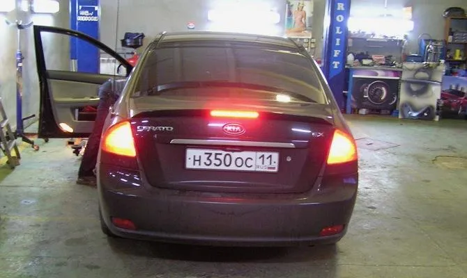
Using a flashing brake light The brake light attracts attention with a flashing red light. Installed at the rear of the vehicle at driver's eye level. Therefore, all drivers who follow this car will definitely see this signal and will be able to respond in time.
A flashing brake light is a simple device, so it is quite possible to do it yourself. To assemble a stop signal with your own hands, it is enough to use a special scheme.
The microvibrator on the K661LA7 chip will generate pulses. A transistor must be used to control the higher supply current. To understand how the brake light works, you must first study the diagram.
2 How to assemble a brake light?
There are many different schemes with which you can collect a brake light.
For example, one of them implies that this device will blink. You can also find a more “advanced” scheme, that is, when the device will work according to a certain algorithm. For example, the signal first flashes once or twice. After turning off the power of the transistor (during the pause), a signal will light up in the middle of the glow. This is what the flickering effect looks like.
To make it easier to understand how these circuits work, you can take one as an example, for example K561LA7.
The development is based on the K561LA7 microcircuit, consisting of 5 elements of the “2I-NOT” type. On the first and second elements is a multivibrator, and on the third – inventory. Thanks to the latter, a useful signal is created at the output, since the inventory separates the multivibrator from the circuit. The function of opening and powering the load on the emitter is performed by the KT816B transistor, which receives a signal through the inventory.
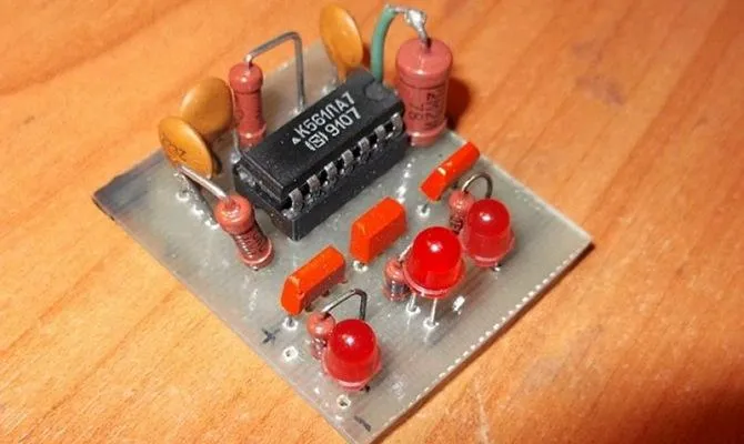
Chip K561LA7
There is also a similar microcircuit, but with an added capacitor and diode. Within one or two pulses, the capacitor charges and then discharges across the transistor in the event of a direct “dip”, resulting in a flashing effect. A diode is added to prevent the capacitor from discharging. The diode is usually not displayed on the diagram, since absolutely any diode can be used. Once you have installed the flashing brake light, no further adjustments are required as it will already work.
The capacitance of the capacitor affects the blinking frequency. For example, on the K561LA7 chip, the supply voltage ranges from 3 to 15 V, so it can be connected directly to the on-board network, which is another advantage.
The signal algorithm is as follows: when you press the brake pedal, the signal flashes for the first 3 seconds, after which it is constantly on. When you press the brake pedal again, everything repeats in exact order.
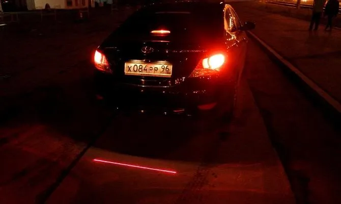
Flashing Algorithm. But the question naturally arises, what about in a traffic jam? Will flashing prevent the driver standing behind from blinding him with light? Want. But it is precisely for this reason that a foot controller with a special G-sensor was invented, designed to increase the visibility of the car when braking.
The controller must be installed in a suitable location and secured in such a way that it is held firmly and securely. The zero position can be set using a special setting mode supplied with the controller.
Now about how to activate this mode. It is quite simple to do this, but you need to perform this procedure with the brake already applied. Therefore, it is easiest to ask a friend for help, who will block the brake and then power the device. After setting the zero position, you will need to adjust the flashing frequency. Usually the controller has 10 frequency modes. They can be different: from slower to almost constant burning. To select a frequency, you need to hold down the button, then determine and set the desired frequency by the number of blinks. Having chosen the best option, you need to release the brake and the cable that feeds the device.
After completing these steps, you can use the button to directly set the threshold at which the flashing will be activated. Its meaning lies in the fact that if the driver does not exceed this threshold, then the stop will light up, as always, and if exceeded, with the specified frequencies. The controller has 12 thresholds, which are also divided into groups. The first 5 thresholds are weak braking zones, the next 3 or 4 are braking with ABS. The latter are designed for 1G overload. Controller prices are relatively low. As a rule, they depend on the load of the connection.
Now you know how to make a brake light and why you need it. It remains only to choose the appropriate scheme and you can start doing it.
